[TUTORIAL] Creating a ship using NURBS modeling
Posted: Mon, 8. Oct 07, 01:31
Modeling with NURBS
Introduction:
This is a very basic instruction on how to create a ship using NURBS. The term NURBS stands for Non-Uniform Rational B-Splines.
The majority of X3 modelers have been using polygon modeling methods for creating their models. With polygon modeling, we generally start with one of the 3D geometry “primitives” such as a box rectangle for example, and then build the model with extrusions etc. There is nothing wrong with polygon modeling. In fact, creating your shape by manipulating polygons is often the best and easiest method.
So why bother with NURBS? One reason is because you can! Perhaps the best reason is because NURBS can offer advantages when you want a very smooth, "rounded" looking model. NURBS are not well suited for creating sharp angles and corners. Sometimes you will see NURBS models referred to as “organic”. This means that the model has a very smooth, flowing appearance similar to most things found in real life nature.
In the case of modeling with polygons, you can for the most part achieve the same result you get with NURBS by applying various smoothing techniques. However, in some cases, if you want nice, even, rounded objects, you may be better off using NURBS. For one thing, you may end up with a very high poly count, or an unsatisfactory distorted mesh from smoothing a sharp-edged polygon. You will need to determine which method is best for your particular application.
3DS Max has an included tutorial on creating a Monkey head using NURBS modeling, which you may find useful in learning this technique. Note: 3DS 9 does not include the NURBS tutorial, but you can download the version 8 instructions from Autodesk.
Here is the simple ship we will build in the following tutorial:
[ external image ]
These instructions are intended for experienced X3 modelers. I will assume you already know the basics of polygon modeling, applying textures, and that you generally know your way around the 3DS Max user interface and menu structure.
Procedure:
1. Draw a Circle in the front viewport. Size doesn’t matter since you can resize your ship when you are completed.
[ external image ]
[ external image ]
2. Center the Circle by adjusting the pivot point. This isn’t entirely necessary, but it’s good practice, and can make things easier later on.
[ external image ]
[ external image ]
3. Convert the Circle to Editable Spline (select and right-click). You may wonder why we are doing this since the Circle is already a Spline! The reason is because by performing this seemingly unnecessary step, we’ll have an object with 8 instead of 16 manipulation points when we convert to NURBS. This will make shape adjustments much easier later on.
[ external image ]
4. Now convert the Circle to NURBS (right-click Convert to NURBS)
Here you see the difference between performing step-3 vs. not doing so:
No “re-conversion to Spline” prior to NURBS. Notice the Control Vertices handles are non-symmetrical:
[ external image ]
Conversion to Spline prior to NURBS conversion:
[ external image ]
5. In the Left Viewport, select the NURBS Circle. In the Modify Panel, select Curve. The Circle will turn Red.
[ external image ]
6. Copy the Circle by Shift-Move drag to the left. Select Independent Copy (if not already selected). Note: there are other ways to perform these basic steps. The method I’m showing is simply one of them.
[ external image ]
7. Perform step-6 a number of times so you have something like this:
[ external image ]
8. Select the first Circle, and “Attach” all the others (Attach Multiple button)
[ external image ]
Now you will have a single NURBS object.
9. Manipulate the Curve Vertices handles to obtain the shape you desire. Note: I repeated steps 7 and 8 to obtain additional “Circles” as my design proceeded, and as I decided I wanted more length towards the rear of the ship.
[ external image ]
[ external image ]
10. Now it’s time to “loft” a surface onto your NURBS Curve. Select your “ship”. If the NURBS Creation Toolbox isn’t already visible, press the button to make it so:
[ external image ]
11. Click the Create U Loft Surface button:
[ external image ]
12 Click on each NURBS Curve in sequential order going from one end to the other.
[ external image ]
A surface will be created as you do this. Right-click when you reach the final Curve at the other end.
[ external image ]
The Surface you have created may have “Normals” inverted (Black outside, colored inside):
[ external image ]
If this is the case, you should “Flip Normals”. This is accomplished by selecting the Surface you have created, and checking the Flip Normals button.
[ external image ]
[ external image ]
13. Continue working on the Control Vertices (step-9) until you have the shape you are looking for:
[ external image ]
You will notice the front and rear of our ship are not “capped”. In other words, they are missing surfaces:
[ external image ]
There are a couple of different ways to “cap” these surfaces. Either we can apply a NURBS Cap Surface now, or we can apply a Cap Holes modifier after we convert our model to a polygon for final modeling and texturing. In this case, I chose to cap the holes later because capping them with a NURBS surface resulted in small unacceptable gaps. Nevertheless, I’ll show you both methods.
14. NURBS Cap Surface – With your NURBS model selected, highlight the NURBS Surface top-level:
[ external image ]
Click the Cap button In the Create Surfaces sub-menu
[ external image ]
Click on the “end” Curve (turns blue):
[ external image ]
The “hole” is now capped with a new NURBS Surface. Do the same for the hole in the front.
[ external image ]
As I mentioned, I chose to leave the holes for capping after conversion to polygon. I’ll explain how to do this when the time comes.
15. Right-click – Convert to Editable Poly:
[ external image ]
16. Now we’ll Cap our front and rear “holes” using the second method – which works best in this particular case. In Modify Panel select Polygon sub-level.
[ external image ]
17. In side view (left in this case), use your cursor to select the rear-most group of poly’s:
[ external image ]
18. In the Edit Geometry rollout, click the Hide Unselected button. This will make it easier for you to work on the area you need to cap.
[ external image ]
19. Select the Edge sub-level.
[ external image ]
20. Using Ctrl-select each edge on the end we want to cap (zooming in as needed):
[ external image ]
[ external image ]
21. Select Cap Hoes from the Modifier List pull-down menu.
[ external image ]
The hole is now filled:
[ external image ]
22. You will notice your Modifier “Stack” has a Cap Holes on top. Let’s go ahead and “collapse” the Stack to get rid of that. One way to do this is right-clip Convert to Editable Poly (just like you did in step-15)
[ external image ]
23. Go to the Polygon sub-level like before (step-16), then the Edit Geometry rollout. Now click Unhide All. Your ship will now be visible with the rear end capped.
[ external image ]
24. Repeat steps 16-23 to cap the front hole.
25. At this point you will use “standard” Bevel, Extrude, Chamfer, etc. polygon manipulation techniques to add whatever remaining details and materials you want.
[ external image ]
Since we are no longer working on NURBS, and since our model for the purposes of these instructions is finished, I now conclude this tutorial.
One of the advantages of using NURBS over Polygon modeling is the increased possibility of a nice smooth, clean model with fewer polygons than sometimes obtained by using polygon MeshSmooth techniques.
[ external image ]
This model has approx. 13,000 polygons – well within acceptable range for X3 ships.
Please feel free to share any NURBS “secrets” you may know. The subject of NURBS modeling in 3DS is complex, and we have only touched the simple basics of one way to create a model using NURBS in this tutorial.
Introduction:
This is a very basic instruction on how to create a ship using NURBS. The term NURBS stands for Non-Uniform Rational B-Splines.
The majority of X3 modelers have been using polygon modeling methods for creating their models. With polygon modeling, we generally start with one of the 3D geometry “primitives” such as a box rectangle for example, and then build the model with extrusions etc. There is nothing wrong with polygon modeling. In fact, creating your shape by manipulating polygons is often the best and easiest method.
So why bother with NURBS? One reason is because you can! Perhaps the best reason is because NURBS can offer advantages when you want a very smooth, "rounded" looking model. NURBS are not well suited for creating sharp angles and corners. Sometimes you will see NURBS models referred to as “organic”. This means that the model has a very smooth, flowing appearance similar to most things found in real life nature.
In the case of modeling with polygons, you can for the most part achieve the same result you get with NURBS by applying various smoothing techniques. However, in some cases, if you want nice, even, rounded objects, you may be better off using NURBS. For one thing, you may end up with a very high poly count, or an unsatisfactory distorted mesh from smoothing a sharp-edged polygon. You will need to determine which method is best for your particular application.
3DS Max has an included tutorial on creating a Monkey head using NURBS modeling, which you may find useful in learning this technique. Note: 3DS 9 does not include the NURBS tutorial, but you can download the version 8 instructions from Autodesk.
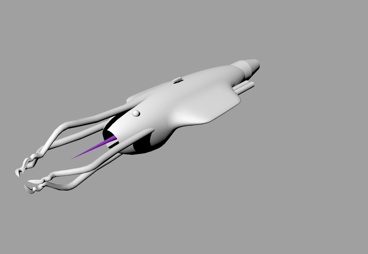
Here is the simple ship we will build in the following tutorial:
[ external image ]
![[ external image ]](http://www.x3dmod.com/ftp/images/M3_plus_nurbs.jpg)
These instructions are intended for experienced X3 modelers. I will assume you already know the basics of polygon modeling, applying textures, and that you generally know your way around the 3DS Max user interface and menu structure.
Procedure:
1. Draw a Circle in the front viewport. Size doesn’t matter since you can resize your ship when you are completed.
[ external image ]
![[ external image ]](http://www.x3dmod.com/ftp/images/nurbs0.jpg)
[ external image ]
![[ external image ]](http://www.x3dmod.com/ftp/images/nurbs1.jpg)
2. Center the Circle by adjusting the pivot point. This isn’t entirely necessary, but it’s good practice, and can make things easier later on.
[ external image ]
![[ external image ]](http://www.x3dmod.com/ftp/images/nurbs2.jpg)
[ external image ]
![[ external image ]](http://www.x3dmod.com/ftp/images/nurbs3.jpg)
3. Convert the Circle to Editable Spline (select and right-click). You may wonder why we are doing this since the Circle is already a Spline! The reason is because by performing this seemingly unnecessary step, we’ll have an object with 8 instead of 16 manipulation points when we convert to NURBS. This will make shape adjustments much easier later on.
[ external image ]
![[ external image ]](http://www.x3dmod.com/ftp/images/nurbs4.jpg)
4. Now convert the Circle to NURBS (right-click Convert to NURBS)
Here you see the difference between performing step-3 vs. not doing so:
No “re-conversion to Spline” prior to NURBS. Notice the Control Vertices handles are non-symmetrical:
[ external image ]
![[ external image ]](http://www.x3dmod.com/ftp/images/nurbs5.jpg)
Conversion to Spline prior to NURBS conversion:
[ external image ]
![[ external image ]](http://www.x3dmod.com/ftp/images/nurbs6.jpg)
5. In the Left Viewport, select the NURBS Circle. In the Modify Panel, select Curve. The Circle will turn Red.
[ external image ]
![[ external image ]](http://www.x3dmod.com/ftp/images/nurbs7.jpg)
6. Copy the Circle by Shift-Move drag to the left. Select Independent Copy (if not already selected). Note: there are other ways to perform these basic steps. The method I’m showing is simply one of them.
[ external image ]
![[ external image ]](http://www.x3dmod.com/ftp/images/nurbs8.jpg)
7. Perform step-6 a number of times so you have something like this:
[ external image ]
![[ external image ]](http://www.x3dmod.com/ftp/images/nurbs9.jpg)
8. Select the first Circle, and “Attach” all the others (Attach Multiple button)
[ external image ]
![[ external image ]](http://www.x3dmod.com/ftp/images/nurbs10.jpg)
Now you will have a single NURBS object.
9. Manipulate the Curve Vertices handles to obtain the shape you desire. Note: I repeated steps 7 and 8 to obtain additional “Circles” as my design proceeded, and as I decided I wanted more length towards the rear of the ship.
[ external image ]
![[ external image ]](http://www.x3dmod.com/ftp/images/nurbs11.jpg)
[ external image ]
![[ external image ]](http://www.x3dmod.com/ftp/images/nurbs12.jpg)
10. Now it’s time to “loft” a surface onto your NURBS Curve. Select your “ship”. If the NURBS Creation Toolbox isn’t already visible, press the button to make it so:
[ external image ]
![[ external image ]](http://www.x3dmod.com/ftp/images/nurbs13.jpg)
11. Click the Create U Loft Surface button:
[ external image ]
![[ external image ]](http://www.x3dmod.com/ftp/images/nurbs14.jpg)
12 Click on each NURBS Curve in sequential order going from one end to the other.
[ external image ]
![[ external image ]](http://www.x3dmod.com/ftp/images/nurbs15.jpg)
A surface will be created as you do this. Right-click when you reach the final Curve at the other end.
[ external image ]
![[ external image ]](http://www.x3dmod.com/ftp/images/nurbs16.jpg)
The Surface you have created may have “Normals” inverted (Black outside, colored inside):
[ external image ]
![[ external image ]](http://www.x3dmod.com/ftp/images/nurbs17.jpg)
If this is the case, you should “Flip Normals”. This is accomplished by selecting the Surface you have created, and checking the Flip Normals button.
[ external image ]
![[ external image ]](http://www.x3dmod.com/ftp/images/nurbs18.jpg)
[ external image ]
![[ external image ]](http://www.x3dmod.com/ftp/images/nurbs19.jpg)
13. Continue working on the Control Vertices (step-9) until you have the shape you are looking for:
[ external image ]
![[ external image ]](http://www.x3dmod.com/ftp/images/nurbs20.jpg)
You will notice the front and rear of our ship are not “capped”. In other words, they are missing surfaces:
[ external image ]
![[ external image ]](http://www.x3dmod.com/ftp/images/nurbs21.jpg)
There are a couple of different ways to “cap” these surfaces. Either we can apply a NURBS Cap Surface now, or we can apply a Cap Holes modifier after we convert our model to a polygon for final modeling and texturing. In this case, I chose to cap the holes later because capping them with a NURBS surface resulted in small unacceptable gaps. Nevertheless, I’ll show you both methods.
14. NURBS Cap Surface – With your NURBS model selected, highlight the NURBS Surface top-level:
[ external image ]
![[ external image ]](http://www.x3dmod.com/ftp/images/nurbs22.jpg)
Click the Cap button In the Create Surfaces sub-menu
[ external image ]
![[ external image ]](http://www.x3dmod.com/ftp/images/nurbs23.jpg)
Click on the “end” Curve (turns blue):
[ external image ]
![[ external image ]](http://www.x3dmod.com/ftp/images/nurbs24.jpg)
The “hole” is now capped with a new NURBS Surface. Do the same for the hole in the front.
[ external image ]
![[ external image ]](http://www.x3dmod.com/ftp/images/nurbs25.jpg)
As I mentioned, I chose to leave the holes for capping after conversion to polygon. I’ll explain how to do this when the time comes.
15. Right-click – Convert to Editable Poly:
[ external image ]
![[ external image ]](http://www.x3dmod.com/ftp/images/nurbs26.jpg)
16. Now we’ll Cap our front and rear “holes” using the second method – which works best in this particular case. In Modify Panel select Polygon sub-level.
[ external image ]
![[ external image ]](http://www.x3dmod.com/ftp/images/nurbs27.jpg)
17. In side view (left in this case), use your cursor to select the rear-most group of poly’s:
[ external image ]
![[ external image ]](http://www.x3dmod.com/ftp/images/nurbs28.jpg)
18. In the Edit Geometry rollout, click the Hide Unselected button. This will make it easier for you to work on the area you need to cap.
[ external image ]
![[ external image ]](http://www.x3dmod.com/ftp/images/nurbs29.jpg)
19. Select the Edge sub-level.
[ external image ]
![[ external image ]](http://www.x3dmod.com/ftp/images/nurbs31.jpg)
20. Using Ctrl-select each edge on the end we want to cap (zooming in as needed):
[ external image ]
![[ external image ]](http://www.x3dmod.com/ftp/images/nurbs32.jpg)
[ external image ]
![[ external image ]](http://www.x3dmod.com/ftp/images/nurbs33.jpg)
21. Select Cap Hoes from the Modifier List pull-down menu.
[ external image ]
![[ external image ]](http://www.x3dmod.com/ftp/images/nurbs34.jpg)
The hole is now filled:
[ external image ]
![[ external image ]](http://www.x3dmod.com/ftp/images/nurbs35.jpg)
22. You will notice your Modifier “Stack” has a Cap Holes on top. Let’s go ahead and “collapse” the Stack to get rid of that. One way to do this is right-clip Convert to Editable Poly (just like you did in step-15)
[ external image ]
![[ external image ]](http://www.x3dmod.com/ftp/images/nurbs36.jpg)
23. Go to the Polygon sub-level like before (step-16), then the Edit Geometry rollout. Now click Unhide All. Your ship will now be visible with the rear end capped.
[ external image ]
![[ external image ]](http://www.x3dmod.com/ftp/images/nurbs37.jpg)
24. Repeat steps 16-23 to cap the front hole.
25. At this point you will use “standard” Bevel, Extrude, Chamfer, etc. polygon manipulation techniques to add whatever remaining details and materials you want.
[ external image ]
![[ external image ]](http://www.x3dmod.com/ftp/images/nurbs39.jpg)
Since we are no longer working on NURBS, and since our model for the purposes of these instructions is finished, I now conclude this tutorial.
One of the advantages of using NURBS over Polygon modeling is the increased possibility of a nice smooth, clean model with fewer polygons than sometimes obtained by using polygon MeshSmooth techniques.
[ external image ]
![[ external image ]](http://www.x3dmod.com/ftp/images/nurbs40.jpg)
This model has approx. 13,000 polygons – well within acceptable range for X3 ships.
Please feel free to share any NURBS “secrets” you may know. The subject of NURBS modeling in 3DS is complex, and we have only touched the simple basics of one way to create a model using NURBS in this tutorial.